Some links on this site are affiliate links. We may earn a commission at no cost to you. Learn more.
Common Welding Defects and How to Fix Them
Common Welding Defects and How to Fix Them
Every welder — from first-day beginners to seasoned professionals — encounters weld defects. The difference between a good welder and a great one is knowing how to identify what went wrong and, more importantly, how to fix it. Recognizing defects early saves time, material, and prevents structural failures down the line.
This guide covers the most common welding defects, their root causes, and practical solutions you can apply immediately.
Porosity
Porosity appears as small holes or cavities within the weld bead, visible on the surface or hidden inside. It occurs when gas becomes trapped in the solidifying weld metal.
Causes
- Contaminated base metal — Oil, grease, rust, paint, or moisture on the surface
- Insufficient shielding gas — Low flow rate, blocked nozzle, or gas leaks
- Wind or drafts — Blowing shielding gas away from the weld pool (MIG/TIG)
- Improper technique — Excessive arc length, wrong travel angle, or moving too fast
- Wet or low-quality electrodes — Moisture absorbed into the flux coating (stick welding)
Solutions
- Clean the base metal thoroughly with a grinder, wire brush, or solvent before welding.
- Verify shielding gas flow rate (20-25 CFH for MIG, 15-20 CFH for TIG).
- Check gas hoses and connections for leaks using a soapy water solution.
- Shield your work area from wind with screens or tarps when welding outdoors.
- Maintain proper stick-out (1/4 to 3/8 inch for MIG).
- Store stick electrodes in a rod oven to prevent moisture absorption.
Undercut
Undercut is a groove melted into the base metal along the toe of the weld that is not filled by weld metal. It creates a stress concentration point that weakens the joint.
Causes
- Excessive amperage — Too much heat melts the base metal edges faster than filler can replace it
- Travel speed too fast — Not enough time for filler metal to fill the joint
- Incorrect electrode angle — Directing too much heat at one edge of the joint
- Improper weaving — Pausing too long at the toes of the weave without adequate fill
Solutions
- Reduce amperage by 5-10% and retest on scrap metal.
- Slow your travel speed to allow proper fill at the weld toes.
- Adjust your electrode or gun angle to distribute heat evenly across both pieces.
- If weaving, pause briefly at the center of the bead and flow filler to the toes.
- Use a welding angle gauge to maintain consistent work angles.
Cracks
Cracks are among the most serious weld defects because they often propagate under load, leading to catastrophic failure. They fall into two categories:
Hot Cracks (Solidification Cracks)
These form as the weld metal solidifies and cools.
Causes:
- Incorrect filler metal selection for the base metal
- Excessive joint restraint (the pieces cannot move as they expand and contract)
- Too-wide weld bead with high depth-to-width ratio
- High sulfur or phosphorus content in the base metal
Solutions:
- Select the correct filler metal for the alloy being welded
- Design joints with enough flexibility to accommodate thermal movement
- Maintain a weld bead width approximately 2-3 times the depth
- Preheat thick sections to reduce thermal stress
Cold Cracks (Hydrogen Cracks)
These appear hours or even days after welding, typically in the heat-affected zone.
Causes:
- Hydrogen absorbed into the weld from moisture, oil, or organic contaminants
- Rapid cooling that creates hard, brittle microstructures in the heat-affected zone
- High restraint in the joint
Solutions:
- Use low-hydrogen electrodes (E7018) and keep them dry
- Preheat the base metal to slow the cooling rate (consult preheat charts for your material thickness)
- Maintain interpass temperatures within the recommended range
- Use a digital thermometer to verify preheat and interpass temperatures
Lack of Fusion
Lack of fusion occurs when the weld metal does not properly bond to the base metal or to a previous weld pass. It creates a weak joint that can fail under load.
Causes
- Insufficient heat input — Amperage too low to melt the base metal
- Travel speed too fast — Not enough time for the heat to penetrate
- Incorrect angle — Arc directed away from the joint edges
- Surface contamination — Oxide layers or mill scale preventing fusion
Solutions
- Increase amperage until you achieve proper penetration on both sides of the joint.
- Slow your travel speed, especially at the start of each weld where the metal is cold.
- Direct the arc at the leading edge of the weld pool and toward the joint interface.
- Grind or wire brush mill scale and oxides from the weld zone.
- Pause briefly at the sides of the joint when weaving to ensure edge fusion.
Lack of Penetration
Unlike lack of fusion (which affects sidewall bonding), lack of penetration means the weld does not reach through the full thickness of the joint at the root.
Causes
- Root opening (gap) too narrow
- Amperage too low for the material thickness
- Electrode or wire diameter too large for the joint geometry
- Travel speed too fast
- Incorrect root face preparation
Solutions
- Increase the root opening to allow the arc to reach the bottom of the joint.
- Increase amperage or use a smaller electrode/wire that can access the root.
- Slow your travel speed to allow deeper melting.
- Ensure proper joint preparation with the correct root face and bevel angle.
Spatter
Spatter consists of small metal droplets thrown from the weld pool that stick to the surrounding base metal. While not always a structural concern, it creates a poor appearance and requires additional cleanup.
Causes
- Voltage too low or too high for the wire feed speed
- Incorrect gas mixture — Pure CO2 produces more spatter than C25
- Dirty contact tip — Causes erratic wire feeding
- Excessive stick-out — Wire extends too far from the contact tip
- Surface contamination — Oil or rust on the base metal
Solutions
- Tune voltage and wire feed speed until the arc sounds like “frying bacon.”
- Use 75/25 Argon/CO2 instead of pure CO2 for MIG welding.
- Replace worn contact tips and clean the nozzle regularly with anti-spatter spray.
- Maintain 1/4 to 3/8 inch stick-out for MIG welding.
- Clean the base metal before welding.
Slag Inclusion
Slag inclusion occurs when flux residues become trapped inside the weld metal instead of floating to the surface. This defect weakens the weld and is common in stick and flux-cored welding.
Causes
- Incomplete slag removal between weld passes
- Amperage too low — Slag does not flow and rise properly
- Travel speed too slow — Excessive slag accumulates faster than it can float out
- Incorrect electrode angle — Slag runs ahead of the arc and gets trapped
Solutions
- Chip and wire brush all slag between passes thoroughly.
- Increase amperage within the electrode’s recommended range.
- Maintain a consistent travel speed that keeps the slag behind the arc.
- Use a slight drag angle for stick welding to keep slag flowing away from the weld pool.
Overlap (Cold Lap)
Overlap occurs when the weld metal flows over the base metal surface without actually fusing to it. It creates a visible ledge at the toe of the weld.
Causes
- Insufficient heat — The weld pool flows but does not melt the base metal
- Travel speed too slow — Excessive filler metal piles up without penetration
- Incorrect technique — Adding too much filler for the heat level
Solutions
- Increase amperage to achieve proper fusion at the weld toes.
- Increase travel speed to match the filler deposition rate.
- Focus the arc on the leading edge of the pool, not on the filler metal.
Burn-Through
Burn-through happens when the arc melts completely through the base metal, creating a hole. It is most common on thin materials.
Causes
- Excessive amperage for the material thickness
- Travel speed too slow — Heat accumulates in one spot
- Excessive root gap — Too much space between the pieces
- Incorrect process — Using stick welding on thin sheet metal
Solutions
- Reduce amperage and use a smaller electrode or wire diameter.
- Increase travel speed to distribute heat over a larger area.
- Use skip welding or stitch welding to prevent heat buildup in one area.
- Use a backing bar or copper heat sink to draw heat away from the backside.
Visual Inspection Checklist
After completing every weld, perform a quick visual inspection:
- Is the bead uniform in width and height along the entire length?
- Are the weld toes smooth with no undercut or overlap?
- Is there any visible porosity on the surface?
- Has the slag been fully removed (stick/FCAW)?
- Does the weld show proper penetration at the root (if visible)?
For critical structural work, consider investing in a weld inspection gauge to measure undercut depth, fillet weld leg size, and reinforcement height.
Final Thoughts
Most welding defects trace back to three root causes: incorrect settings, poor preparation, or improper technique. When you encounter a defect, resist the urge to simply grind it out and reweld. Instead, identify the root cause and correct it before proceeding. Consistent, defect-free welding comes from understanding the relationship between heat, filler, and travel speed — and adjusting them as conditions change.
Related Articles
Porosity and shielding failures are closely connected to your gas choice — understanding welding shielding gases explains how different blends affect arc stability and contamination risk. Many defects stem from incorrect machine setup. The MIG welder setup guide walks through voltage, wire feed speed, and polarity settings to get you dialed in before you weld on real work. For welders preparing for a certification test where defects will be evaluated by a CWI, the AWS D1.1 certification guide covers the visual acceptance criteria and common failure points.

Frank Ciervo
Certified Welder & Founder of The Welder's Guide
Get our free Welding Safety Checklist — delivered to your inbox.
No spam. Unsubscribe anytime.
Recommended Product
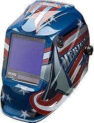
Lincoln Electric Viking 3350 Auto-Darkening Helmet
A premium auto-darkening welding helmet with 1/1/1/1 optical clarity, 4C lens technology, and a wide viewing area. Comfortable for all-day use.
- ✓ 4C lens technology
- ✓ 1/1/1/1 optical clarity
- ✓ Wide 12.5 sq in view
- ✓ Grind mode
As an Amazon Associate, we earn from qualifying purchases.
Get Your Free Welding Safety Checklist
Join thousands of readers. Expert tips and guides delivered to your inbox — no spam, ever.
No spam. Unsubscribe anytime. View our Privacy Policy.
Affiliate Disclosure
Some of the links on this page are affiliate links. If you click on one of these links and make a purchase, we may receive a small commission at no additional cost to you. This helps support our site and allows us to continue providing free content.
We only recommend products we believe in. All opinions are our own. We are a participant in the Amazon Services LLC Associates Program, an affiliate advertising program designed to provide a means for us to earn fees by linking to Amazon.com and affiliated sites.