Welding arc blow: Causes, diagnosis, and handoff
Quick answer
Welding arc blow is directional arc deflection caused by an unbalanced magnetic field around the welding circuit, often involving DC current, ferromagnetic steel, joint geometry, residual magnetism, or the work-return path. Confirm that pattern before changing the approved setup: unstable arc length, a poor work connection, shielding loss, and consumable faults can look similar.
Common questions
- What causes arc blow in welding?
- Arc blow occurs when magnetic forces deflect the arc from its intended path. The welding-current path, return location, joint geometry, residual magnetism, ferromagnetic material, and DC current can contribute. Similar symptoms can also come from technique, connections, shielding, or consumables, so direction and repeatability matter.
- Is arc blow more common with AC or DC welding?
- Persistent magnetic arc blow is more strongly associated with DC because its magnetic field has a steady direction. AC may reduce magnetic deflection in some approved applications, but changing current type or polarity is not a universal fix and may require a different qualified procedure.
- Can moving the work clamp stop arc blow?
- Changing the work-return location can change the current path and may change the direction or severity of arc blow. Do this only after de-energizing as required and under the equipment manual, WPS, and responsible welding authority; one clamp location or travel direction is not correct for every circuit.
- Can a finished weld be accepted after arc blow?
- Not from appearance alone. Arc blow can contribute to undercut, lack of fusion, irregular penetration, porosity, or slag entrapment. Record the event and use the inspection and acceptance criteria required by the drawing, WPS, code, contract, or repair procedure.
Source note: Reviewed October 9, 2026 against current TWI magnetic arc-blow guidance, Miller equipment documentation, and OSHA welding controls. The applicable WPS, code, equipment manual, consumable data, inspection plan, and responsible welding authority control changes and acceptance for a specific weld.
Welding arc blow: Causes, diagnosis, and handoff
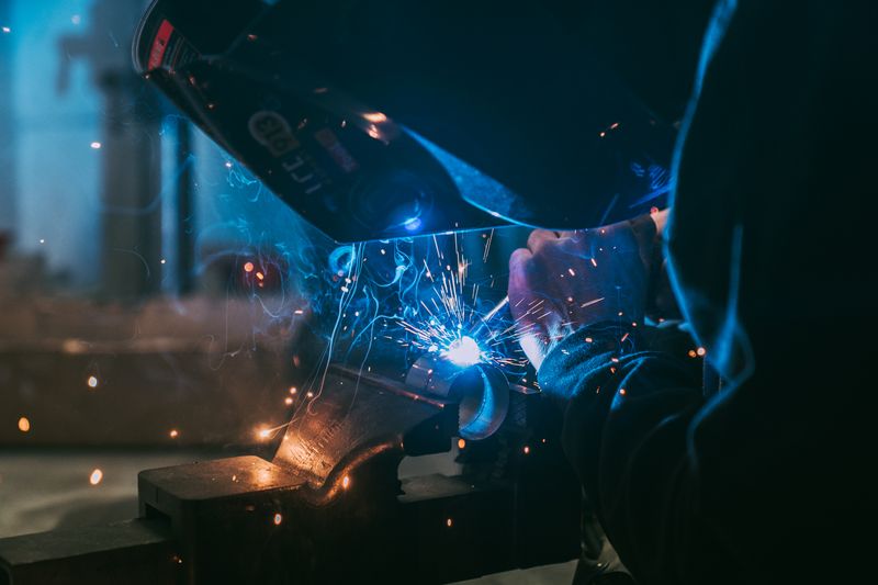
Welding arc blow is a repeatable, directional deflection of the arc caused by magnetic forces around the welding circuit. It is most often associated with DC welding on ferromagnetic steel, especially near joint ends, corners, root gaps, or magnetized components. The work-return path and residual magnetism can both distort the field around the arc.
Do not label every wandering or harsh arc as arc blow. An overlong arc, a poor work connection, wind stripping shielding gas, a damaged consumable, or unstable torch technique can create similar noise, spatter, and bead shape. Confirm the pattern before asking for a procedure change.
Stop random adjustments first
If the arc is leaving the joint or the puddle is no longer controllable, stop depositing production weld metal. Keep the part identified, record the location, and preserve the approved setup. Do not hide the area with another pass.
Follow the equipment manual and site procedure before touching the electrode, gun, torch, work lead, or connection. OSHA requires properly installed equipment and instructed, qualified operators. Maintain the required PPE, screens, ventilation, fire prevention, and hot-work controls while diagnosing the weld.
The work lead carries welding current; it is not a substitute for the equipment grounding conductor. Never create an improvised return through a building, crane, cylinder, bearing, piping, lifting chain, or other unintended path.
Arc-blow diagnostic matrix
Use all four columns together. One visual clue is not enough to diagnose magnetic arc blow.
| Symptom and timing | Process and current | Material and joint position | Most useful interpretation and next evidence |
|---|---|---|---|
| Arc bends consistently toward one side, forward, or backward; behavior strengthens near a plate end, corner, tack, or root | Often DC SMAW, GTAW, GMAW, FCAW, or SAW | Ferromagnetic steel; open root, narrow groove, pipe fit-up, corner, or joint end | Magnetic/current-path branch is plausible. Record deflection direction, travel direction, return location, and exact joint position. |
| Arc direction changes predictably when an authorized person changes the return location or weld direction | Usually DC; one controlled variable changes | Steel joint where current must funnel around a gap, fixture, or end | Strong current-path clue. Preserve both configurations and results for the welding supervisor rather than declaring a universal clamp position. |
| Arc stays deflected after basic setup checks and is worst at a steel root gap | Often DC root pass | Steel with possible residual magnetism from handling, inspection, forming, storage, or prior current | Request field measurement and engineering review. Surface attraction or a phone compass is not an acceptance measurement. |
| Arc becomes unstable mainly when arc length, stickout, torch angle, or hand position changes | Any current type and process | Any weldable material or position | Technique or process stability may be more likely. Restore the documented arc length and position on a practice coupon. |
| Arc cuts out, stubs, or changes when the lead or clamp moves; a connection heats or discolors | Any arc process | Any material; often independent of joint position | Suspect a loose, dirty, damaged, undersized, or poorly seated connection. De-energize and inspect to the manual; do not call this proof of arc blow. |
| Porosity or oxidation worsens when a door, fan, extractor, or outdoor wind changes | Gas-shielded GMAW, FCAW, or GTAW | Any material; exposed positions are more vulnerable | Shielding loss is more likely. Maintain required ventilation and isolate airflow without defeating fume control. |
| Problem follows one electrode, wire spool, tungsten, contact tip, or polarity setup | Process-specific | Any material; not tied consistently to a joint end or direction | Check classification, condition, storage, polarity, feed path, and manufacturer data before pursuing magnetism. |
| Arc is unstable on AC or on nonferromagnetic material without a repeatable directional pattern | AC process or aluminum/copper alloy work | Any position | Persistent magnetic arc blow is less likely, but do not diagnose by elimination alone. Check the equipment, connections, shielding, consumable, and technique. |
The welding-rod sticking diagnostic owns arc-start and contact failures. The common welding defects guide covers the broader defect taxonomy; this page focuses on isolating arc deflection.
Run a controlled diagnosis
1. Capture the approved baseline
Before anything changes, record:
- Job, drawing, weld ID, joint location, material specification, thickness, and fit-up
- Welding process, power-source model, current type, polarity, amperage/voltage or program, and consumable classification
- WPS number and revision, position, travel direction, pass number, and whether the event occurred at a start, tack, root, fill, cap, corner, or joint end
- Work-lead size, condition, connection point, cable route, fixtures, nearby magnets, and other active welding circuits
- Direction and severity of the arc movement, plus photos or video if the site permits them
For production or code work, compare the setup with the applicable WPS rather than a generic settings chart. The WPS, PQR, and qualification-record guide explains which record supports procedure control.
2. Exclude the common look-alikes
On suitable practice material, verify the documented arc length, torch or electrode angle, stickout, travel speed, consumable, polarity, and machine setup. Inspect accessible leads and work connections only after the equipment is safely de-energized as required.
For gas-shielded processes, confirm the specified gas path, nozzle condition, and environmental controls. Do not switch off required extraction to make an arc appear steadier. For SMAW, verify electrode classification, storage condition, and polarity with the exact product data. The general stick-welding technique guide can refresh terminology, but the WPS and consumable data govern the job.
3. Look for a directional relationship
Arc blow usually has structure: it may repeat at the same joint end, pull consistently toward one side of a root gap, or change when the current path changes. Record the relationship among the arc, travel direction, joint geometry, and work-return location.
Published instructions are configuration-specific. For example, TWI discusses welding toward a return connection for some MMA conditions, while a Miller manual for multiple power sources specifies a different cable-and-travel arrangement for that system. That is why “always weld toward the clamp” or “always weld away from it” is unsafe as a universal rule.
4. Escalate suspected residual magnetism
If a directional arc problem remains after setup, technique, connection, shielding, and consumable checks, ask the responsible welding authority whether magnetic-field measurement is required. TWI describes measurement at the joint gap with an appropriate gaussmeter for some pipe applications, but its published threshold is a rule of thumb—not a universal acceptance limit.
Demagnetization, compensation coils, cable wrapping, multiple returns, run-on/run-off tabs, sequencing changes, and altered tack plans require an engineered or procedure-approved method. Do not improvise current paths or copy a coil/current recipe from another job.
Procedure-controlled options, not universal fixes
| Option the responsible authority may evaluate | Why it may help | Required control |
|---|---|---|
| Relocate or add an approved work return | Changes current distribution and the magnetic field around the joint | Equipment manual, cable capacity, safe isolation, WPS, and site electrical controls |
| Change travel direction or weld sequence | Changes how current funnels through the work near starts, ends, corners, and gaps | Drawing, distortion plan, heat-input/interpass limits, and supervisor approval |
| Use a shorter arc or a permitted lower current | Reduces the arc length or magnetic force available for deflection | Stay within the consumable data and qualified WPS; verify fusion and penetration |
| Change AC/DC, polarity, process, or consumable | AC can reduce persistent directional deflection in some applications | Formal procedure review; the change may be an essential variable requiring requalification |
| Add approved tacks or run-on/run-off tabs | Can change joint restraint, geometry, and end effects | Approved joint design, tack procedure, removal plan, and inspection requirements |
| Measure and demagnetize the component | Addresses residual magnetism rather than only changing technique | Qualified personnel, calibrated equipment, documented target, and an engineered method |
If a proposed action changes current type, polarity, process, filler metal, heat input, joint design, or another controlled variable, stop and obtain the required approval. A troubleshooting article cannot authorize a WPS change.
Inspect the weld, not just the arc
Arc blow can move heat and filler away from the intended location. Possible results include undercut, lack of fusion, irregular penetration, slag entrapment, porosity, excessive spatter, and an uneven bead profile. None is confirmed or cleared by appearance alone.
Mark the affected length and follow the drawing, code, contract, WPS, inspection plan, and repair procedure. A production repair may require removal to sound metal, inspection of the excavation, an approved repair WPS, reinspection, and documented disposition. Use the weld inspection and testing guide to understand what visual, surface, volumetric, and destructive methods can and cannot establish.
Evidence and handoff checklist
Give the welding supervisor, inspector, engineer, or procedure owner a record they can act on:
- Job, weld ID, drawing, material, joint, position, pass, and exact location recorded
- WPS number/revision and equipment/consumable documentation confirmed
- Process, AC/DC, polarity, settings, travel direction, and arc-length baseline recorded
- Work-return locations, lead routes, fixtures, magnets, and simultaneous welding circuits mapped
- Deflection direction, timing, repeatability, and changes near roots, tacks, corners, or ends documented
- Technique, connection, shielding, and consumable look-alikes checked one at a time
- Any authorized comparison test and its restored baseline documented
- Suspected nonconforming weld metal identified and protected from further work
- Required magnetic measurement, inspection, repair, or WPS review assigned to a named authority
- Final disposition and acceptance evidence attached to the job record
Next step: preserve the successful control
After the responsible authority approves a control, repeat it on representative material and document the result. Then update only the records the quality system permits—do not quietly turn a one-off workaround into shop practice.
If the main symptom was a sticking electrode rather than directional deflection, continue with the rod-sticking diagnostic. If arc blow may have affected weld quality, move to the required inspection and testing path before acceptance.
Sources and scope
- TWI: How do you prevent arc blow?
- TWI: What is magnetic arc blow?
- Miller equipment manual with arc-blow and multiple-power-source guidance
- OSHA 1910.254: Arc welding and cutting
- OSHA 1910.252: Welding, cutting, ventilation, and fire-prevention requirements
Sources describe general mechanisms and controls, not approval for a particular weld. Use the current equipment manual, WPS, code edition, inspection plan, and site safety program that apply to the work in front of you.

The Welder's Guide Editorial Team
Independent trade-focused editorial team