Flux-Core Welding Polarity: DCEN or DCEP?
Quick answer
Set flux-core welding polarity from the exact wire manufacturer's current data sheet. Many common E71T-11 self-shielded wires run DCEN, and many gas-shielded wires run DCEP, but neither pattern is universal: some self-shielded products require DCEP.
Common questions
- What polarity should I use for gasless flux-core wire?
- Use the polarity specified on the exact wire package or manufacturer data sheet. Many common E71T-11 self-shielded wires require DCEN, but some self-shielded flux-cored wires require DCEP, so gasless does not prove the correct polarity.
- Can flux-core welding use DCEP?
- Yes. Many gas-shielded flux-cored wires use DCEP, and some self-shielded wires do too. Confirm the product name, classification, diameter, shielding requirements, and polarity in the manufacturer's documentation.
- What happens when flux-core polarity is wrong?
- The arc may become harsh or unstable, with excessive spatter, porosity, poor bead shape, or difficult slag removal. Those symptoms can also come from feed, settings, stickout, contamination, gas, or work-connection problems, so verify the setup before diagnosing by appearance.
Source note: Reviewed August 14, 2026 against current or available Hobart Brothers and Lincoln Electric filler-metal documentation plus OSHA welding and hot-work guidance. Product data sheets, the machine manual, an approved WPS, and the responsible welding authority control a specific job.
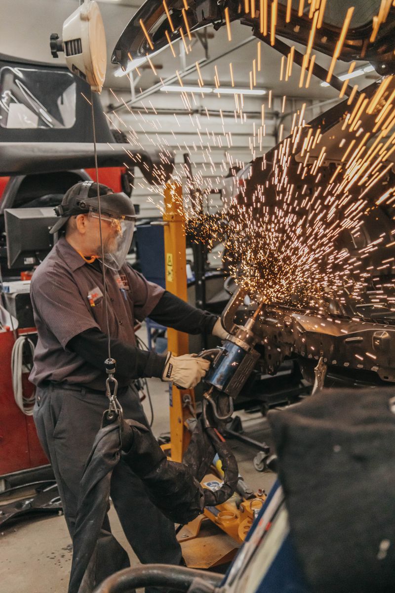
The correct flux-core welding polarity is the polarity listed for the exact wire, not a rule inferred from the words “flux core” or “gasless.” Many common E71T-11 self-shielded wires run DC electrode negative (DCEN), while many gas-shielded flux-cored wires run DC electrode positive (DCEP). Exceptions exist, including self-shielded wires designed for DCEP.
Before moving any leads, identify the wire by manufacturer, product name, classification, and diameter. Then check its current data sheet and your welder’s manual. If you are choosing between common spool sizes, use the .030 vs. .035 flux-core wire decision aid to check the data-sheet range, feed path, joint, position, and WPS before loading the wire. On structural, pressure, vehicle, lifting, or other life-safety work, the approved welding procedure specification (WPS) and responsible welding authority also control the setup.
DCEN vs. DCEP at a glance
Polarity describes how the electrode and work circuit connect to a direct-current power source.
| Polarity | Gun/electrode connection | Work lead connection | Also called |
|---|---|---|---|
| DCEN | Negative (−) | Positive (+) | DC− or straight polarity |
| DCEP | Positive (+) | Negative (−) | DC+ or reverse polarity |
The “electrode” in FCAW is the wire emerging from the gun. The work lead completes the welding circuit; calling it a “ground” can be confusing because protective grounding and the welding work connection serve different purposes.
Some small flux-core machines have fixed polarity. Multi-process and MIG/FCAW machines may use front-panel sockets, internal studs, or an electronic selection. Follow the machine manual and disconnect input power before opening a compartment or changing cable connections. Never assume terminal position from a photo of another model.
Why there is no universal flux-core polarity
Flux-cored arc welding includes self-shielded FCAW (FCAW-S) and gas-shielded FCAW (FCAW-G). The flux system, alloy, classification, intended application, and manufacturer design affect the required current and shielding.
These documented examples show why the wire data sheet matters:
| Wire | Process and classification | Manufacturer-specified polarity |
|---|---|---|
| Hobart Fabshield 21B | Self-shielded, E71T-11 | DCEN |
| Lincoln Electric Innershield NR-211-MP | Self-shielded, E71T-11 | DC− (DCEN) |
| Hobart FabCO 711M | Gas-shielded, E71T-1C H8 / E71T-1M H8 | DCEP |
| Hobart Fabshield 4 | Self-shielded, E70T-4 | DCEP |
Hobart Brothers likewise says many popular E71T-8 and E71T-11 self-shielded wires require DCEN, while other self- and gas-shielded wires require DCEP. Classification narrows the search, but the product data sheet is the final practical check.
If you are still choosing a process, start with the site’s comparison of flux-cored wire vs. solid wire. Polarity is only one part of that decision; shielding, wire suitability, joint requirements, cleanup, wind, and equipment capacity matter too.
How to verify flux-core polarity before welding
Use this sequence whenever you install a new spool, change brands, or move a machine between solid wire and FCAW.
- Identify the exact wire. Record the manufacturer, product name, AWS classification, diameter, and lot where available. A partial label such as “.035 flux core” is not enough.
- Read the manufacturer’s current data sheet. Find “type of current,” “polarity,” or the operating-procedure table. Also verify whether shielding gas is required, which gas or blend is permitted, and the allowed positions and passes.
- Check machine compatibility. Confirm that the welder can supply the required polarity, output range, and wire size. Read its polarity-change procedure rather than relying on connector location alone.
- De-energize and connect correctly. Turn the machine off and disconnect input power as its manual directs. Connect the gun/electrode cable and work lead to the specified terminals, tighten them correctly, and reinstall covers.
- Finish the wire setup. Fit the specified drive roll and contact tip, set minimal adequate drive pressure, and use the data sheet’s starting voltage, wire-feed speed, and contact-tip-to-work distance. Add the specified gas only for a wire that requires it.
- Make a controlled test weld. Use clean scrap of the same material and thickness in a safe area. Inspect it using the method appropriate to the work, then adjust one variable at a time within the approved procedure.
The broader MIG welder setup guide covers the feed path, drive rolls, work connection, gas system, and test bead. Use the MIG welding settings chart only as starting context; the flux-core wire data sheet remains the better source for wire-specific ranges.
Wrong-polarity symptoms and what they really mean
Wrong polarity can produce a weld that looks or sounds obviously wrong, but appearance alone cannot prove the cause.
| Symptom | Polarity-related possibility | Check before changing polarity |
|---|---|---|
| Harsh, erratic, or unstable arc | Wire is connected opposite its specification | Product data sheet, loose terminals, work connection, voltage, and feed speed |
| Excessive spatter | Incorrect polarity can upset arc behavior | Stickout, travel angle, contamination, worn tip, and voltage/feed balance |
| Porosity or worm tracks | Wrong polarity may disrupt the wire’s shielding and slag system | Wire storage, base-metal contamination, wind, gas requirement, gas leaks, and stickout |
| Poor bead profile or apparent fusion | The wire may not be operating as designed | Joint preparation, travel speed, heat input, position, and procedure limits |
| Slag is unusually difficult to remove | Polarity may be wrong for the flux system | Technique, bead shape, interpass cleaning, and the exact wire specification |
Hobart’s guidance for Fabshield 21B warns that using the wrong polarity can cause porosity and difficult slag removal. However, similar defects can come from damp or damaged wire, an unsuitable gas, poor electrical contact, an incorrect contact-tip-to-work distance, or dirty base metal.
Use the weld defects troubleshooting guide to separate porosity, slag inclusions, lack of fusion, and other discontinuities. Do not reverse polarity as a trial-and-error adjustment when the documentation is missing. Stop, preserve the wire label, and get the current data sheet from the manufacturer or supplier.
Common setup mistakes after switching from MIG
A machine that ran solid-wire MIG correctly can still be misconfigured after an FCAW changeover. Check for these mistakes:
- Polarity was never changed. Solid-wire GMAW commonly uses DCEP, while the newly installed self-shielded wire may specify DCEN.
- The gas valve was treated as the process selector. Turning off the cylinder does not change electrical polarity or make gas-shielded wire self-shielding.
- The old smooth drive roll stayed installed. Tubular wire often needs the manufacturer’s specified knurled roll and only enough pressure to feed consistently.
- Settings were copied from solid wire. Voltage, wire-feed speed, stickout, travel angle, and usable positions are wire-specific.
- The work connection is poor. Attach the clamp to clean metal as directed and inspect the lead, terminals, and connection before blaming the arc.
- Slag was not removed. Clean between passes where required and before judging the final surface.
For repeat feeding trouble, work through MIG wire-feed problems and troubleshooting before increasing drive pressure.
Safety checks before a polarity test
Polarity troubleshooting still involves energized welding equipment, hot metal, sparks, ultraviolet radiation, and fumes. Apply the same controls used for production welding.
- Fumes and ventilation: Identify the wire, base metal, coatings, and safety data sheets. Keep your head out of the plume and use general ventilation, local exhaust, and respiratory protection as required by the hazard assessment. Do not weld in a confined space without the applicable entry, atmospheric, and ventilation controls.
- Electrical hazards: Inspect the gun, leads, insulation, terminals, and work connection. Keep equipment and clothing dry, use the manufacturer’s shutdown procedure before changing connections, and do not touch live parts.
- Fire and hot work: Remove or protect combustibles, control sparks and slag on every side of the work, keep suitable fire-extinguishing equipment ready, and use the required permit and fire watch. Never weld a container that held a flammable material unless an approved procedure has made it safe.
- PPE and nearby workers: Use an appropriate welding helmet and filter shade, safety glasses, gloves, flame-resistant protective clothing, and suitable footwear. Screen the arc and protect others from radiation, sparks, and hot work.
OSHA identifies welding fume, ultraviolet radiation, burns, eye damage, electrical shock, and fire as core hazards. The site’s welding safety essentials and hot-work permit and fire-watch checklist can help organize the controls, but workplace rules and applicable regulations take priority.
What to check next
Once the wire and polarity match, record the product, diameter, polarity, gas, voltage, wire-feed speed, stickout, position, and observed result. If the arc is still unstable, check the work connection and feed path before changing settings. If the arc is stable but the weld shows porosity or slag inclusions, investigate contamination, wire condition, shielding, technique, and procedure limits.
Use the weld defect glossary worksheet to document the symptom and make one controlled change at a time. Practice notes do not approve a critical weld; use qualified procedures, personnel, and inspection wherever failure could injure someone.
Sources and scope
- Hobart Brothers: polarity must be verified from the wire data sheet
- Hobart Fabshield 21B data sheet: self-shielded E71T-11, DCEN
- Lincoln Electric Innershield NR-211-MP data sheet: self-shielded E71T-11, DC−
- Hobart FabCO 711M data sheet: gas-shielded E71T-1, DCEP
- Hobart Fabshield 4 data sheet: self-shielded E70T-4, DCEP
- OSHA welding, cutting, and brazing hazards and controls
- OSHA construction welding fire-prevention requirements
This guide explains setup and diagnosis; it is not a welding procedure or weld-acceptance standard. Product literature can change, so use the current documentation for the wire in hand.

The Welder's Guide Editorial Team
Independent trade-focused editorial team