Slag inclusion in welding: Causes and prevention
Quick answer
Slag inclusion is nonmetallic flux residue trapped within weld metal or between weld passes. Before changing settings, stop, identify the process and affected pass, inspect joint access and bead shape, and verify cleaning, angle, travel, and approved heat-input variables. Visual inspection can reveal surface slag and profiles that trap it, but it cannot rule out a buried inclusion. The WPS, governing code, inspector or engineer, and consumable manufacturer control acceptance, examination, and repair.
Common questions
- What causes slag inclusion in welding?
- Common cause families are incomplete cleaning between passes, a bead or joint profile that creates a slag pocket, poor access, slag running ahead of the arc, incorrect manipulation or angle, and heat-input or travel conditions that prevent adequate fusion and slag escape. Diagnose the pattern before changing an approved variable.
- Can you see slag inclusion on a weld?
- Only when the inclusion breaks the surface or is exposed during cleaning or excavation. Visual inspection can find surface residue and risky bead profiles, but a clean-looking surface does not prove that the weld is free of buried slag.
- How do you prevent slag inclusion in stick welding?
- Use the electrode, polarity, parameters, and technique required by the WPS and manufacturer; maintain access and a profile that can be cleaned; keep slag behind the arc; and remove residue from every pass, toe, restart, and crevice before depositing the next pass.
- Does slag inclusion always require weld repair?
- No universal answer applies. Acceptance and repair depend on the applicable code and edition, project specification, weld location, service, indication dimensions, and inspection results. The authorized inspector or engineer must make or approve the disposition.
Source note: Reviewed October 23, 2026 against current ISO 5817:2023 scope, TWI slag-inclusion and radiography guidance, U.S. Navy and IAEA welding training references, AWS visual-examination guidance, and OSHA welding controls. These sources support diagnosis and prevention; the applicable WPS, code edition, project specification, inspector or engineer, and manufacturer instructions control production decisions.
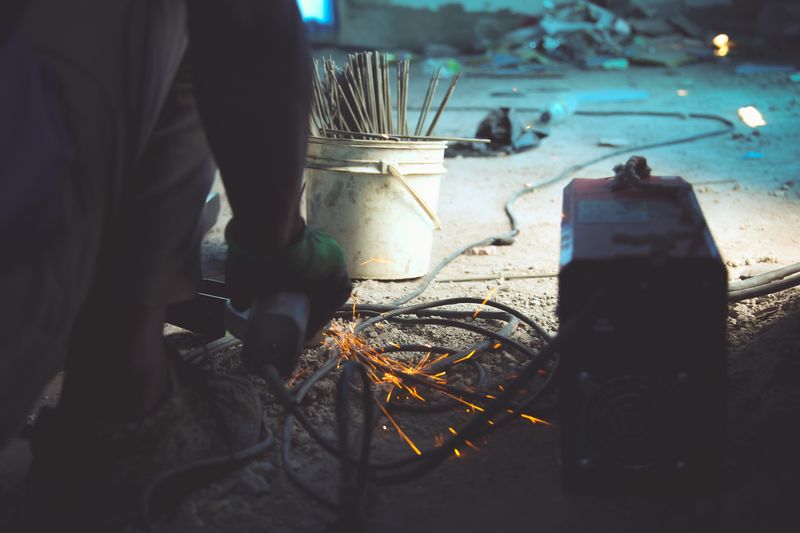
Slag inclusion in welding: Causes and prevention
Slag inclusion in welding means nonmetallic flux residue has become trapped inside the weld or between weld passes. Stop before covering a suspected area. Record the process, pass, settings, consumable, and pattern, then check access, bead profile, travel and angle, heat-input evidence, and cleaning against the approved welding procedure specification (WPS).
Do not accept, reject, grind, or reweld a production joint from appearance alone. A smooth surface can hide an inclusion, and a visible indication does not supply its depth or the acceptance rule.
What a slag inclusion is—and is not
Flux in shielded metal arc welding (SMAW or stick), flux-cored arc welding (FCAW), and submerged arc welding (SAW) helps protect and shape the weld pool. Its lower-density residue should rise and solidify over the bead. An inclusion forms when some of that residue is overrun or sealed into the weld metal.
In multipass welds, an uncleaned toe, undercut, restart, or narrow groove can become a pocket under the next pass. Slag inclusion often overlaps with lack of fusion, but one is trapped material while the other is failure to fuse at an interface.
Solid-wire MIG/GMAW and TIG/GTAW do not create a heavy flux slag layer. If an indication is found in one of those welds, consider oxide or silicate residue, tungsten or another metallic inclusion, contamination, or lack of fusion instead of naming it from appearance. The common welding defects guide helps separate these defect families.
What visual inspection can establish
After the weld has cooled and the surface is cleaned as required, visual inspection can reveal:
- Slag at a toe, crater, restart, or between passes
- Surface-breaking lines, pockets, or cavities exposed during cleaning
- Convex or uneven passes with deep toe valleys
- Undercut, poor overlap, and access that can trap residue
Visual inspection cannot rule out slag below a sound-looking surface, measure its internal extent, or prove fitness for service. Penetrant and magnetic-particle testing are surface methods. Radiography commonly reveals elongated slag lines, while ultrasonic capability depends on the joint, material, indication orientation, procedure, and operator. The inspection plan and examiner select the required method. See the weld inspection and testing guide for the roles and limits of VT, PT, MT, RT, and UT.
Slag inclusion diagnostic matrix
Use observations as evidence, not as permission to change a controlled variable. Return to the documented baseline and test one allowed correction at a time on representative practice material.
| Process | Joint access | Bead profile | Travel and angle | Heat/input evidence | Interpass cleaning |
|---|---|---|---|---|---|
| SMAW / stick | A large electrode, narrow groove, tight root, or poor sight line can leave unreachable corners. | Convex passes and toe valleys create pockets; undercut can lock slag beside the bead. | Slag running ahead of the arc, an inconsistent arc length, excessive weave, or poor work angle can overrun residue. | A cold-looking ropey bead may suggest insufficient fusion; high current combined with fast travel can undercut. Verify actual values against the WPS and electrode data. | Chip and brush every pass, toe, restart, and crater. Grind only when the procedure permits and brushing cannot expose clean metal. |
| FCAW-S or FCAW-G | Deep grooves, backing details, restricted gun access, and an unsuitable wire size can hide toe lines. | Irregular overlap, a crowned bead, or undercut between passes can form a continuous trap. | Wrong travel direction or angle for the specific wire, excessive manipulation, or outrunning the puddle can let slag lead the arc. | Check voltage, wire feed, current, contact-tip-to-work distance, travel, and polarity as a system; do not assume “more heat” is the cure. | Remove the wire’s slag system completely and follow its data sheet. Pay special attention to sidewalls and restarts. |
| SAW | Groove geometry, bead placement, and limited access beneath flux can leave sidewall pockets. | Poor bead placement or overlap can create channels that the next run seals. | Travel and electrode placement must keep fusion and bead overlap within the qualified procedure. | Confirm current, voltage, travel speed, wire/flux combination, and heat input from recorded parameters. | Remove fused slag between runs and inspect the full bead before reapplying flux. Follow flux handling and recovery rules. |
| Solid-wire GMAW or GTAW | Restricted access can still promote oxide entrapment or lack of fusion. | Silicate islands, an uneven profile, or a suspicious line do not by themselves prove flux-slag inclusion. | Check torch angle, arc placement, filler timing, and travel for fusion-related clues. | Compare parameters, shielding, surface condition, and filler data with the WPS. | Clean oxides and surface residue as required; ask the examiner to classify the indication rather than assuming it is slag. |
If the pattern is mainly a groove at the weld edge, use the welding undercut diagnostic. If the rod repeatedly freezes to the work and disrupts bead control, work through the welding rod sticking guide before treating the resulting profile as an isolated cleaning problem.
Diagnose the cause in a controlled sequence
1. Preserve the evidence
Stop before another pass hides the area. Mark whether it is at a root, sidewall, toe, weave edge, restart, tack, or position transition. Photograph it if allowed.
2. Confirm process and consumable controls
Check the WPS revision, joint, position, pass sequence, consumable classification and size, polarity, manufacturer range, storage, and required temperatures. A familiar-looking wire or electrode may have different technique requirements.
3. Inspect access and the previous pass
Check whether the arc and cleaning tools can reach both sidewalls and the root. Look for a narrow angle, oversized electrode, convex bead, undercut, abrupt restart, or uneven overlap. The welding joint types guide explains how groove and fillet geometry changes access.
4. Check cleaning before tuning parameters
Remove residue using the approved chipping, brushing, or grinding method. Use material-dedicated tools where contamination control requires them, and do not grind away acceptance evidence before authorization. “Self-peeling” slag is not proof that every toe and crater is clean.
5. Evaluate one permitted change
Compare actual current, voltage, travel, arc length or stickout, angle, and bead placement with approved guidance. Change one permitted variable on practice material, then inspect the entire bead. A change that releases slag but creates undercut or lack of fusion is not a solution.
Prevention checklist for every pass
- Prepare access: Use the specified groove, root opening, fit-up, consumable size, and pass sequence.
- Hold a cleanable profile: Place and overlap passes so they do not leave deep toe valleys or abrupt ridges.
- Control the slag line: Keep the arc where it can fuse the intended interface without allowing slag to run ahead of the puddle.
- Stay within the procedure: Verify polarity and actual parameters; do not improvise outside the qualified range.
- Clean and inspect: Remove slag from the complete pass, including toes, craters, tacks, and restarts, before continuing.
- Stop on recurrence: Repeated inclusions call for supervisor, inspector, or procedure-owner review—not another cover pass.
Acceptance, excavation, and repair
There is no universal slag-inclusion acceptance limit or automatic repair rule. ISO 5817, structural codes, pressure and piping codes, owner specifications, and engineered repair documents have different scopes and criteria. The applicable drawing, contract, WPS, governing code and edition, inspection plan, and authorized inspector or engineer control the disposition.
Do not assume a grinder has removed the full inclusion because the visible line disappears. An approved repair path may require mapping the indication, controlled excavation to sound metal, examination of the cavity, rewelding under a repair WPS, and repeat inspection. For a noncritical practice coupon, expose the indication and review the cross-section with an instructor; never transfer that practice decision to structural, pressure, vehicle, lifting, or life-safety work.
Work safely while cleaning or repairing
Slag removal and grinding add flying-particle, noise, spark, and dust hazards to the arc, fume, radiation, electrical, and fire hazards of welding. Complete the required hazard assessment and hot-work permit; isolate combustibles; use the specified welding helmet, safety glasses, face protection, gloves, hearing protection, flame-resistant clothing, screens, and fire watch.
Use effective general or local exhaust ventilation and keep the plume out of the breathing zone. Outdoor work does not guarantee adequate ventilation, and confined-space welding requires its own entry, atmospheric, ventilation, respiratory, attendant, and rescue controls. The welding safety essentials and hot-work permit checklist provide a starting point; site rules and applicable regulations control.
Next step: document the pattern before changing settings
Use the weld defect glossary worksheet to record the process, joint, pass, location, bead profile, cleaning result, and one-variable practice tests. For production work, give that record to the welding supervisor, inspector, or engineer and wait for the required inspection and disposition.
Sources and scope
- TWI: Slag inclusions—identification, causes, and prevention
- U.S. Navy training manual: Welding quality control
- IAEA Training Course Series No. 11: Non-destructive testing
- AWS: Pocket Guide for Visual Examination of Welds
- ISO 5817:2023: Quality levels for imperfections
- TWI: Principles and limitations of radiography
- OSHA: Hot-work and welding controls
- OSHA 1926.353: Ventilation and protection
These references support general identification, cause control, inspection limits, and safety boundaries. They do not authorize a production setting change, acceptance decision, examination plan, or repair.

The Welder's Guide Editorial Team
Independent trade-focused editorial team