MIG welding gas flow rate chart and adjustment guide
Quick answer
Set MIG shielding gas while gas is flowing, using the machine and wire manufacturer's specified range. If neither gives a value, 20–25 CFH (about 9–12 L/min) is a common reference for indoor shop work, but the correct flow changes with the gun, nozzle, gas, transfer mode, position, and airflow.
How to set MIG shielding gas flow
Set and verify MIG shielding gas flow without confusing pressure with delivered flow.
1. Confirm the procedure
Check the welder manual, filler-metal data sheet, WPS, gas, wire, transfer mode, and nozzle before choosing a flow.
2. Inspect the gas path
Secure the cylinder and inspect the regulator, hose, connections, gun, diffuser, O-rings, and nozzle for damage, blockage, or leaks.
3. Start gas flow safely
Use the machine's gas-test or purge control when provided; otherwise follow its procedure for preventing wire feed while testing. Keep the gun pointed away from people.
4. Set the flowing rate
Adjust the flowmeter while gas is moving, not from a static pressure reading. Begin inside the manufacturer's specified range.
5. Verify at the nozzle
When available, compare the cylinder-side reading with a nozzle flow tester to identify restrictions or leaks downstream.
6. Change one condition at a time
Control drafts, clean the nozzle, correct stickout and angle, then make small flow changes within approved procedures and evaluate the weld by the required inspection method.
Common questions
- What is a good gas flow rate for MIG welding?
- Use the rate specified by the welder and wire manufacturers. When neither provides one, 20–25 CFH, or about 9–12 L/min, is a common indoor reference, but some equipment and aluminum or stainless applications specify substantially higher flow.
- Is MIG regulator pressure the same as gas flow rate?
- No. Pressure describes force per unit area, while flow rate describes gas volume delivered over time. Set and read MIG shielding gas in CFH or L/min while gas is actually flowing.
- Can too much shielding gas cause porosity?
- Yes. Excess flow can become turbulent and pull surrounding air into the shielding envelope. Before increasing flow, also check drafts, nozzle spatter, leaks, connections, stickout, torch angle, and gas supply.
Source note: Reviewed August 7, 2026 against current Miller owner-manual guidance, Lincoln Electric equipment instructions, Fronius MIG/MAG training material, and OSHA hot-work guidance. These are reference values, not independently tested settings; the equipment manual, filler-metal data sheet, WPS, and responsible welding authority control the job.
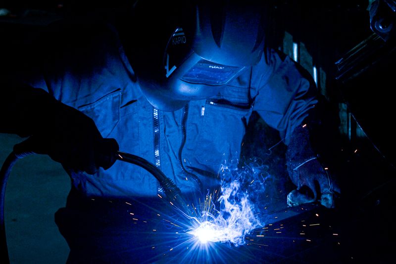
MIG welds can develop porosity even when the cylinder gauge looks normal. The reason is simple: cylinder pressure, regulator pressure, and gas flow at the nozzle are different measurements.
For many indoor shop setups, 20–25 cubic feet per hour (CFH), about 9–12 liters per minute (L/min), is a useful reference point. It is not a universal setting. Set flow with gas moving, then follow the welder manual, wire data sheet, welding procedure specification (WPS), and gas-system instructions.
MIG welding gas flow rate chart
Use this chart to convert a specified flow rate; do not treat every row as a recommended setting. Values are rounded from 1 CFH = 0.472 L/min.
| CFH | L/min | CFH | L/min |
|---|---|---|---|
| 10 | 4.7 | 28 | 13.2 |
| 12 | 5.7 | 30 | 14.2 |
| 15 | 7.1 | 35 | 16.5 |
| 18 | 8.5 | 40 | 18.9 |
| 20 | 9.4 | 45 | 21.2 |
| 25 | 11.8 | 50 | 23.6 |
To convert another value:
- CFH to L/min: multiply CFH by 0.472
- L/min to CFH: multiply L/min by 2.119
Manufacturer ranges show why the manual matters. One current Miller manual calls 20–25 CFH typical and says to check the wire maker’s recommendation. Other Miller equipment documentation specifies 15–30 CFH for CO₂, 25–45 CFH for mixed gas, and 35–45 CFH for aluminum MIG with argon. A Lincoln manual specifies 15–20 CFH in ordinary conditions and 20–25 CFH for drafty or out-of-position work on that machine.
Those are equipment-specific instructions, not contradictions to average away. If you are also selecting voltage and wire speed, keep that broader job on the MIG welding settings chart.
Pressure is not flow rate
Pressure is force per unit area, commonly displayed in PSI, bar, or kPa. Flow rate is volume delivered over time, displayed in CFH or L/min. Cylinder pressure can tell you that compressed gas remains, but it does not prove that the correct amount reaches the weld.
A regulator may control pressure, while a flow gauge or flowmeter estimates delivered gas under particular conditions. Read the value while gas is flowing through the gun, using the gas-test function or the equipment maker’s safe setup method. A nozzle flow tester can help compare actual delivery at the torch with the cylinder-side indication.
For the full connection sequence, see how to set up a MIG welder.
How to adjust MIG gas flow
Start with the approved baseline, then address the condition that changed. Do not keep turning up the flowmeter to hide a fault.
| Condition | Best first action | Flow decision |
|---|---|---|
| Still indoor air, standard nozzle | Clean the nozzle and use normal contact-tip-to-work distance | Start within the equipment and wire maker’s range |
| Larger nozzle or wider gas envelope | Confirm the gun/nozzle procedure | A higher flow may be specified; do not guess from bore size alone |
| Narrow or recessed-access nozzle | Keep the correct stickout and avoid steep gun angles | More flow may become turbulent rather than improve coverage |
| Draft, fan, or open door | Remove or redirect the airflow without defeating fume control | Increase only within the approved range after controlling the draft |
| Outdoor work | Use screens or choose a suitable wind-tolerant process | Gas-shielded MIG may remain unreliable; consider approved self-shielded FCAW instead |
| Short-circuit transfer | Match gas and wire to the written procedure | Common shop ranges may apply, but use the machine chart |
| Spray or pulsed-spray transfer | Confirm an appropriate argon-rich blend, wire, position, and program | Higher deposition, nozzle size, and manufacturer programs may require different flow |
| 100% CO₂, argon blend, or tri-mix | Use a regulator/flowmeter calibrated and approved for that gas | Do not assume the same indicated value means identical delivered flow on every device |
| Aluminum with 100% argon | Follow the spool-gun/push-pull system and wire instructions | Some current manuals specify much higher flow than small-steel-machine references |
Gas choice affects arc behavior and transfer mode, but this page does not replace a gas-selection guide. Use understanding MIG shielding gases to match the gas to mild steel, stainless steel, or aluminum before adjusting delivery.
Too little gas versus too much gas
Low and high flow can produce similar symptoms, including porosity. Diagnose the whole path rather than assuming every pinhole means “more gas.”
Signs of inadequate shielding
- Surface or subsurface porosity
- Oxidation, soot, or abnormal discoloration
- A draft-sensitive, inconsistent arc
- Coverage that improves only when airflow is removed
Possible causes include an empty or closed cylinder, a low setting, a leak, a pinched hose, a blocked diffuser, spatter in the nozzle, excessive stickout, steep gun angle, or airflow across the arc.
Signs of excessive or turbulent flow
- Porosity remains or worsens as flow increases
- A loud gas rush at the nozzle
- Rapid gas consumption without better coverage
- An unstable shield around a narrow, obstructed, or dirty nozzle
Fronius troubleshooting guidance specifically identifies turbulence from excessive shielding-gas flow as a porosity cause. Reduce flow to the approved range and correct nozzle condition, torch distance, and angle.
Porosity diagnosis in the right order
- Stop and identify the requirement. Confirm the WPS, manual, wire, gas, polarity, transfer mode, and acceptable inspection criteria.
- Control the environment. Shield the arc from drafts, but never block required ventilation or place extraction so it strips away shielding gas.
- Inspect the nozzle and diffuser. Remove spatter using approved tools and replace damaged consumables.
- Check the entire gas path. Inspect the cylinder connection, regulator, hose, solenoid path, gun fittings, seals, and O-rings. Use an approved leak-detection method; never use a flame.
- Measure while flowing. Set the specified CFH or L/min with gas moving and, when possible, verify delivery at the nozzle.
- Check non-gas causes. Clean oil, moisture, coatings, rust, and mill scale as the procedure requires. Verify consumable storage and base-metal condition.
- Make one controlled change. Adjust within the approved range and evaluate the result using the inspection method required for the work.
The common welding defects guide covers porosity alongside cracks, undercut, incomplete fusion, and other discontinuities.
Safety limits before testing gas flow
Shielding gases can displace oxygen, and welding creates fumes, heat, sparks, ultraviolet radiation, and fire hazards. Secure cylinders upright, protect valves, inspect the system, use the required hot-work controls and PPE, and provide ventilation or fume extraction suited to the material and space.
Do not solve a shielding problem by turning off effective exposure controls. OSHA notes that fume-extraction guns require extraction and shielding-gas flow to be carefully balanced. Confined-space and coded work need the applicable permits, atmospheric controls, qualified procedures, and supervision. Review welding safety essentials before changing the work area.
What to check next
Once delivery is stable, use the shielding-gas guide to confirm the blend, the MIG settings chart for voltage and wire-feed context, and the weld defect glossary worksheet to record symptoms before changing another variable. If outdoor airflow cannot be controlled, compare flux-cored versus solid wire rather than wasting gas on an unstable shield.
Sources and scope
- Miller MIG owner manual: typical 20–25 CFH and flowing adjustment
- Miller Multimatic 220 manual: process- and gas-specific ranges
- Lincoln Electric Handy MIG instructions: ordinary and drafty-condition ranges
- Fronius MIG/MAG training: factors that change nozzle gas consumption
- OSHA welding hot-work guidance
Use these sources to understand the range of manufacturer guidance. They do not override the manual, filler-metal instructions, WPS, governing code, or responsible welding authority for a specific job.
Continue the MIG setup and diagnosis
Connect measured gas delivery to gas selection, machine parameters, defects, and outdoor process choices.
- Understand shielding gases
Choose a gas or blend for mild steel, stainless steel, aluminum, and the intended transfer mode.
- MIG welding settings chart
Review voltage and wire-feed starting points without confusing them with gas delivery.
- Set up a MIG welder
Work through polarity, wire, gas connections, drive rolls, and a controlled test setup.
- Troubleshoot welding defects
Check porosity alongside contamination, technique, and other defect causes.
- Compare flux-cored and solid wire
Decide whether self-shielded wire is more suitable when outdoor airflow cannot be controlled.
- Open the weld defect worksheet
Record symptoms, conditions, and one controlled change at a time.

The Welder's Guide Editorial Team
Independent trade-focused editorial team