Welding undercut: Causes, prevention, and disposition
Quick answer
Welding undercut is a groove melted into the base metal along a weld toe that is not filled with weld metal. Stop adding passes, confirm that the indication is undercut, record where it occurs, then isolate travel, heat and arc length, angle, deposition, fit-up, position, and feed stability one variable at a time within the approved WPS. Acceptance and repair come from the governing drawing, code edition, contract, and inspection plan—not a universal depth limit.
Common questions
- What causes undercut in welding?
- Common cause families are excessive travel relative to deposition, excessive current or a wide arc, incorrect arc length or voltage, poor work or travel angle, uneven manipulation, difficult position or fit-up, and unstable wire delivery. The pattern on the joint matters, so change one approved variable at a time rather than assuming every groove needs less amperage.
- Is any welding undercut acceptable?
- Sometimes, but there is no universal allowable depth. Acceptance can depend on the governing code and edition, service, loading, material thickness, weld type, indication length, and project requirements. An inspector must apply the criteria named by the drawing, contract, or inspection plan.
- How do you prevent undercut in stick welding?
- First confirm the approved electrode classification, diameter, polarity, current range, position, and technique. Then check arc length, travel rate, electrode angle, bead placement, and whether the puddle is filling both toes. Test only permitted adjustments on representative practice material before returning to production.
- Can you grind welding undercut smooth?
- Only when the governing repair or disposition permits it and enough sound material will remain. Grinding can remove additional base metal and cannot restore missing section thickness. Some jobs require weld repair and reinspection; others may permit blending or accept the indication as-is.
Source note: Reviewed October 16, 2026 against the current ISO 6520-1 classification page, ISO 5817:2023 scope, AWS D1.1:2025 listing, TWI shape-imperfection guidance, SSAB and Lincoln Electric process guidance, and OSHA welding controls. Manufacturer guidance is process- and product-specific; the applicable WPS, drawing, code edition, contract, and responsible welding authority control production work.
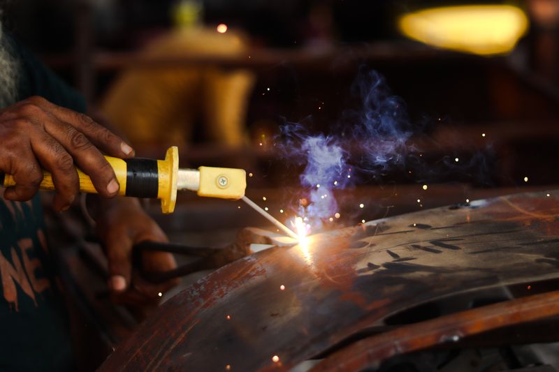
Welding undercut: Causes, prevention, and disposition
Welding undercut is a groove melted into the base metal at a weld toe and left unfilled by weld metal. The right response is not automatically “turn down the amps”: identify the indication, map its pattern, isolate the controlling variable, and follow the required acceptance or repair path.
On production work, stop before covering the area. Preserve the weld ID and setup, mark the affected length, and notify the person named by the quality plan. Keep required PPE, ventilation, screens, fire prevention, and hot-work controls in place.
Identify undercut before changing settings
Undercut follows an edge where weld metal meets parent metal. TWI defines it as an irregular groove in the parent metal at the toe of a run. It can appear at the surface of the completed weld, beside an intermediate pass, or at the bore surface of some single-sided pipe welds.
Look at the cleaned, accessible surface under the lighting and surface condition required by the inspection procedure. Trace both toes and note whether the groove is on one side, both sides, the face, the root side, or only near starts, stops, tacks, and position changes.
Do not confuse these conditions:
- Toe undercut is a groove in the parent metal directly beside the weld toe.
- Root-side undercut describes a groove along a weld edge on the root or bore side. A centered recess across the root surface may instead be root concavity or underfill.
- Underfill is a weld face or root surface that finishes below the intended profile because the joint lacks deposited weld metal; it is not necessarily a groove cut into the base metal at the toe.
- Overlap is weld metal that flows onto the parent metal without fusing. It forms a lip rather than a groove.
- Lack of fusion is failure to fuse at the base-metal interface or between passes. It may be planar or hidden, so a smooth surface does not rule it out.
The common welding defects guide places these indications in the broader defect family. The weld inspection and testing guide explains why visual inspection, surface methods, and volumetric methods answer different questions.
Use the pattern to isolate welding undercut causes
Record the pattern before changing anything. A correction that helps one process and position can create lack of fusion, excessive reinforcement, or another problem elsewhere.
| What you observe | Variable family to check first | Controlled next step |
|---|---|---|
| A narrow bead and grooves at both toes | Travel is high relative to filler deposition | Return to the documented baseline; on representative practice material, evaluate an approved travel or deposition adjustment. |
| A wide, fluid bead with washed-away edges | Current, voltage, arc length, or total heat input may be excessive | Verify actual machine values, leads, polarity, and arc length against the WPS and equipment or consumable data. |
| Undercut stays mostly on one side | Work angle, travel angle, arc placement, fit-up, or gravity is unbalanced | Check joint alignment and sight line; center the arc and support both toes using the approved technique. |
| Grooves appear at the edges of a weave | Oscillation width, rhythm, or edge fill is inconsistent | Use only the weave width and manipulation allowed by the WPS; evaluate smaller movement or controlled edge timing on practice material. |
| The upper toe of a horizontal fillet is affected | Position, puddle sag, placement, and deposition rate are interacting | Confirm position, fillet size, fit-up, pass sequence, angle, and approved parameter window before adjusting technique. |
| The indication appears near a tack, joint end, or changing gap | Tie-in, fit-up, arc blow, or a start/stop transition may control it | Record the exact location; check tack preparation, gap, travel transition, and directional arc behavior. |
| Wire-feed sound, arc length, and bead width vary together | Contact tip, liner, drive system, stickout, connection, or feed stability may be involved | Restore stable delivery and connections to the equipment manual before tuning the weld profile. |
The relationship between heat and fill matters more than a slogan. High current can melt a deeper edge, yet a wide arc with too little filler or travel that outruns the puddle can also leave a groove. Reducing current blindly may trade undercut for lack of fusion. Slowing down blindly may overfill the joint or exceed heat-input limits.
For GMAW and FCAW, consider voltage or arc-length control, wire feed speed, travel speed, contact-tip-to-work distance, torch angle, transfer mode, and feed consistency as a system. Lincoln Electric notes in process-specific guidance that higher travel speeds can increase undercut risk, but its listed procedures are starting points for those applications—not universal settings.
For SMAW, verify electrode classification and diameter, polarity, approved current range, arc length, travel, work angle, and manipulation. For GTAW, include current control, arc length, travel, torch angle, and filler timing. The welding position guide can help label the position, while the approved WPS still controls the production technique.
Run an observation-to-adjustment check
1. Protect and document the weld
Record the job, drawing, weld ID, material, joint type, position, pass, and exact location. Photograph the cleaned indication if site rules allow. Do not grind, peen, blend, or add a wash pass before the required inspector sees it.
2. Capture the approved baseline
Record the WPS number and revision, process, current type and polarity, displayed settings, consumable classification and diameter, shielding gas, travel direction, technique, and equipment condition. For wire processes, add wire-feed behavior, contact tip, liner, drive-roll condition, stickout, and gas delivery. The MIG settings guide is educational; it does not replace the job’s WPS or equipment data.
3. Change one permitted variable
Start with the pattern in the table and test on suitable representative material. Keep every change inside the WPS and manufacturer limits, then return to baseline before testing another cause. If the needed change falls outside the qualified range or changes process, polarity, filler, joint design, or another controlled variable, stop and escalate to the welding supervisor or procedure owner.
4. Recheck the complete bead
A change is not successful merely because the groove disappears. Check weld size, toe blend, reinforcement, fusion-related clues, penetration requirements, starts and stops, and any position transition. Record the before-and-after result so the approved control can be repeated.
Measure and decide against the governing criteria
A visual gauge can help measure accessible profile dimensions after the surface is prepared as the inspection procedure requires. It does not identify hidden lack of fusion, prove that a weld is fit for service, or choose the acceptance standard.
There is no universal welding undercut tolerance. AWS D1.1 applies to structural steel and contains inspection and acceptance requirements, while ISO 5817 specifies quality levels for imperfections in certain fusion-welded joints. Neither title makes its criteria applicable to every pressure weld, pipeline, vehicle, lifting point, aluminum part, repair, or owner specification.
Before accepting or rejecting the weld, confirm:
- The drawing, contract, owner specification, code, and exact edition
- The weld type, material, thickness, service, loading, and inspection stage covered by that requirement
- How depth, length, location, and continuity must be evaluated
- Whether another requirement is more restrictive
- Who is authorized to inspect, accept, or assign repair
Repair only under an approved disposition
Do not assume grinding makes undercut acceptable. Blending can remove the sharp profile, but it also removes base metal and may violate minimum thickness or surface-finish requirements. Adding a “wash pass” can conceal the original boundary, change heat input, and still leave lack of fusion.
Depending on the governing requirements, the disposition may be acceptance as-is, approved blending with thickness verification, removal to sound metal and weld repair, or replacement. A repair may require an approved repair WPS, controlled excavation, inspection of the prepared area, rewelding by qualified personnel, and repeat examination. Keep the disposition and final inspection with the weld record.
Next step: connect the correction to inspection
For practice work, use the weld defect glossary worksheet to record the pattern and one-variable tests. For production work, hand the same evidence to the welding supervisor, inspector, or procedure owner and wait for the required disposition.
If undercut appeared after the arc pulled consistently away from the joint, use the welding arc blow diagnostic. If the indication may extend below the visible surface, follow the specified inspection and testing path rather than treating appearance as proof.
Sources and scope
- ISO 6520-1:2007: Classification of geometric imperfections
- ISO 5817:2023: Quality levels for imperfections
- AWS D1.1/D1.1M:2025: Structural Welding Code—Steel
- TWI: Geometric shape imperfections, types and causes
- SSAB: Undercut causes and remedial actions
- Lincoln Electric: AC-STT process guide
- OSHA 1910.252: Welding, cutting, and brazing requirements
These sources describe classification, process clues, and safety or quality frameworks. They do not authorize a setting change, acceptance decision, or repair for a particular weld.

The Welder's Guide Editorial Team
Independent trade-focused editorial team