MIG welding porosity causes: A controlled diagnostic
Quick answer
MIG weld porosity means gas became trapped as the weld solidified. Start with the documented machine, wire, gas, material, and WPS baseline, then isolate shielding delivery, drafts, gas-path faults, contamination, and technique one variable at a time. Do not cover porous metal with another bead; use the applicable repair and inspection procedure.
Common questions
- Why am I getting porosity in my MIG welds?
- Common causes include lost or turbulent shielding, a leak or restriction in the gas path, drafts, a dirty nozzle, contaminated base metal or wire, and technique that moves the shielding envelope away from the pool. Record the baseline and change one variable at a time so one fault does not hide another.
- Can too much shielding gas cause MIG porosity?
- Yes. Excessive flow can become turbulent and draw surrounding air into the shielding envelope. Return to the value specified by the machine, gun, wire, or approved procedure, then check drafts, leaks, restrictions, nozzle condition, angle, and contact-tip-to-work distance before adjusting again.
- Can you weld over porosity?
- Do not assume another bead will make a porous weld acceptable. Follow the governing repair procedure, which may require removing affected weld metal to sound metal, inspecting the excavation, correcting the cause, rewelding to an approved WPS, and completing the required inspection.
- Does a smooth-looking MIG bead prove the porosity is gone?
- No. Porosity can be below the surface, and grinding can expose cavities that were not visible before. Acceptance depends on the applicable drawing, WPS, code, contract, and inspection method—not appearance alone.
Source note: Reviewed September 30, 2026 against current Miller and Hobart GMAW defect guidance, Miller equipment-manual resources, ESAB aluminum guidance, and OSHA hot-work, ventilation, electrical, and compressed-gas requirements. The exact machine, gun, wire, gas, WPS, acceptance document, and site safety program control a specific weld.
MIG welding porosity causes: A controlled diagnostic
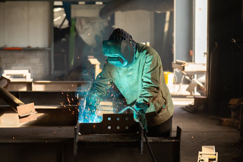
MIG welding porosity is gas trapped in the weld metal as it solidifies. The usual source is ineffective shielding or contamination, but turning up the flowmeter is not a reliable diagnosis. Excess flow can create turbulence, while a leak, blocked diffuser, draft, dirty joint, or changing gun position can produce the same pinholes.
Return to a documented baseline and test one variable at a time on suitable practice material. That preserves evidence, prevents random setting changes, and helps distinguish a gas-delivery fault from preparation or technique.
Match the symptom and timing to the first check
| What you observe | What it may indicate | First controlled check |
|---|---|---|
| Porosity starts suddenly on every bead | Gas supply, valve, connection, hose, gun, or a new environmental condition | Confirm the correct gas is connected and reaches the nozzle as the manual specifies |
| The bead changes when a door, fan, or extractor starts | Shielding gas is being displaced | Reposition airflow without defeating required fume control |
| Pinholes occur only over part of the joint | Local oil, moisture, coating, rust, scale, or contamination trapped in a seam | Prepare a clean representative coupon and compare |
| Porosity changes when the gun cable bends or the gun rotates | Intermittent restriction, leak, loose connection, or damaged gun component | De-energize the equipment and inspect the external gas path |
| Cavities appear after grinding an apparently smooth bead | Subsurface porosity was present | Stop treating appearance as acceptance and follow the required inspection path |
| The problem began after changing wire, gas, program, or polarity | Process components no longer match | Compare every label and connection with the manual, wire data sheet, and WPS |
| The arc pops as well as leaving pores | Shielding, contamination, feed, setting, or connection faults may overlap | Stabilize shielding, then use the MIG popping diagnostic if the arc remains erratic |
Visible pinholes are only one form of porosity. Rounded pores, clusters, or elongated cavities can remain below the surface and may require the inspection method specified for the job. The common welding defects guide keeps the broader defect taxonomy; this guide focuses on isolating GMAW porosity.
Make the test safe first
Use the PPE, screens, ventilation, respiratory protection, and hot-work controls required for the material and location. Keep your head out of the plume. Position extraction to control fumes without stripping shielding gas from the weld; do not simply switch off ventilation to make a test bead.
Secure compressed-gas cylinders and protect them from damage. Never use a flame to find a leak. Before removing the nozzle, diffuser, liner, gun connection, or machine panels, release the trigger, shut down and isolate energy as the manufacturer and workplace procedure require. Internal gas-solenoid, electrical, and regulator faults belong with qualified service personnel.
Unknown coatings, galvanized or stainless material, confined spaces, and used containers require a specific hazard assessment. Do not grind or heat an unidentified coating, and never make a test weld on a container merely because it appears empty.
Establish the exact process baseline
Write down the machine and gun model, base metal, joint, wire classification and diameter, shielding gas, polarity, program, voltage, wire-feed setting, contact tip, nozzle, and recent changes. Photograph labels if the setup may be disturbed.
Confirm whether the process is:
- Gas-shielded GMAW with solid or metal-cored wire
- Gas-shielded FCAW, which also depends on external shielding but has wire-specific slag, polarity, and technique requirements
- Self-shielded FCAW, which has no external shielding-gas path to troubleshoot
Use the exact owner’s manual, gun parts diagram, wire data sheet, and approved WPS as the baseline. The complete MIG setup guide is a useful checklist, but it does not replace those controlling documents.
1. Prove gas delivery at the nozzle
Confirm the cylinder label matches the procedure; do not identify compressed gas by cylinder color alone. Check that valves, regulator or flowmeter, and any machine purge function are used exactly as their manufacturers direct.
Read flow while gas is moving, not only from a static gauge. If the equipment procedure permits, a compatible nozzle flow tester can help compare delivery at the gun with the cylinder-side indication. Use the specified range for the actual equipment, wire, transfer mode, material, and position—there is no single flow setting for every MIG weld.
The MIG gas-flow guide explains flowing measurements and why “more gas” can make coverage worse.
2. Separate drafts from turbulence
Close or redirect an open door, fan, or cross-draft for one controlled test while maintaining required ventilation. Use suitable welding screens when the safety plan permits them. If coverage improves, environmental airflow was a meaningful variable.
If porosity remains after increasing gas, restore the documented setting. A high flow through a dirty, narrow, damaged, or poorly positioned nozzle can become turbulent and entrain surrounding air. Check the nozzle, gun angle, and contact-tip-to-work distance against the exact gun, wire, or WPS guidance rather than using a universal number.
3. Inspect the complete gas path
With the system safely isolated, trace the path from cylinder to nozzle:
- Look for a damaged regulator or flowmeter, loose connection, cut hose, sharp bend, or crushed section.
- Check the machine and gun connections, seals, and O-rings identified in the parts diagram.
- Remove spatter from the nozzle with the approved tool and inspect the diffuser for blocked ports or damage.
- Use only a manufacturer-approved leak-detection method and solution.
- Replace damaged parts with specified components; do not improvise seals or open energized equipment.
A cylinder gauge can show remaining pressure while a downstream leak or restriction prevents stable coverage at the pool.
4. Isolate base-metal and wire contamination
Prepare a clean coupon of the same known material and thickness. Remove oil using an approved cleaner before mechanical preparation, and keep chlorinated-solvent vapors away from welding. Clean rust, scale, paint, moisture, and coatings to the WPS or manufacturer requirement.
Inspect exposed wire for rust, dirt, lubricant, or poor storage history. Check whether contamination could be trapped between joint faces or drawn from the back of the joint. If the clean coupon welds without pores while the original joint does not, preparation or joint contamination moves to the top of the list.
5. Hold technique constant
Use the gun angle, travel speed, contact-tip-to-work distance, and start/stop technique specified for the wire and procedure. Support the cable so its weight does not pull the gun away or change a marginal connection.
If pores occur mainly at starts or stops, observe gas delivery and torch position through the complete weld cycle, then follow the machine’s timing and crater instructions. Do not invent a preflow, postflow, stickout, or dwell value.
6. Check material- and process-specific causes
Verify the gas, wire, polarity, program, and transfer mode as one compatible system. The shielding-gas guide explains gas selection, while the label, manual, and WPS decide the actual setup.
Aluminum needs its own preparation and storage controls because hydrogen from moisture and hydrocarbon contamination can form porosity as the metal solidifies. Use the current aluminum-wire and equipment instructions for cleaning, handling, liners, feeding, and shielding. Do not transfer carbon-steel preparation rules or gas settings to aluminum.
Can you weld over porosity?
Do not cover porosity with another bead and assume it is repaired. Additional weld metal can conceal or trap the discontinuity, and the heat cycle does not prove the original cause is gone.
The governing repair procedure may require you to:
- Record and mark the affected area.
- Determine the applicable drawing, WPS, code, contract, and acceptance criteria.
- Remove affected weld metal to sound metal by an approved method.
- Inspect the excavation as required.
- Correct the root cause before rewelding.
- Reweld to an approved procedure and complete the specified inspection or testing.
For structural, pressure, vehicle, lifting, fall-protection, or other failure-critical work, stop and involve the responsible welding supervisor, inspector, engineer, or repair authority. A visually smooth repair is not proof of fusion, internal soundness, or code acceptance.
Next step: document the successful change
After porosity disappears on a representative coupon, restore the job baseline and record the one change that fixed it. Then apply the required inspection criteria. Use the weld inspection and testing guide to understand why visual inspection, penetrant, radiography, ultrasonic testing, or destructive tests answer different questions.
If the gas path was the cause, return to the MIG gas-flow guide for measurement and leak-isolation context. If the arc still bangs or stubs after shielding is stable, continue with the popping and sputtering diagnostic rather than changing several controls together.
Sources and scope
- Miller: troubleshooting common MIG weld defects
- Hobart Brothers: MIG troubleshooting for metal-cored and solid wire
- Miller owner’s-manual lookup by model or serial number
- ESAB: troubleshooting aluminum welding problems
- OSHA 1910.252: welding, cutting, ventilation, and hot-work requirements
- OSHA 1910.101: compressed-gas requirements
Manufacturer documents, regulations, codes, and approved procedures can change. Use the current editions and site requirements that apply to the equipment, material, and weld in front of you.

The Welder's Guide Editorial Team
Independent trade-focused editorial team