MIG welder popping and sputtering: Diagnose it in 7 checks
Quick answer
Repeated hard pops, wire stubbing, or an arc that cuts in and out usually means the short-circuit cycle is unstable. Start with the machine's chart, then check the work connection, voltage-to-wire-feed balance, feed path, shielding, polarity, and technique in that order. Change one condition at a time on scrap that matches the job.
Common questions
- Why does my MIG welder keep popping?
- Hard, irregular popping often means the wire is stubbing into the work or the arc is being interrupted. Possible causes include an incorrect voltage-to-wire-feed relationship, restricted wire delivery, a poor work connection, contamination, incorrect polarity, inadequate shielding, or inconsistent stickout.
- Is a crackling sound normal when MIG welding?
- A fast, even crackle can be normal during stable short-circuit GMAW. Slow bangs, the gun pushing back, wire burning into the tip, or the arc repeatedly cutting out are troubleshooting clues rather than a target sound.
- Should I turn up voltage or wire speed when a MIG welder pops?
- Do not adjust either control blindly. Return to the machine or wire chart for the actual material, wire, gas, and joint, then change one variable at a time on a representative practice coupon. Wire stubbing can indicate too little voltage for the selected wire feed, but feed resistance or a poor connection can produce a similar symptom.
Source note: Reviewed September 4, 2026 against Miller GMAW process and parameter guidance, a Lincoln Electric torch troubleshooting manual, and OSHA welding ventilation and fire-prevention requirements. The exact machine, gun, wire, gas, procedure, and safety documentation control a specific weld.
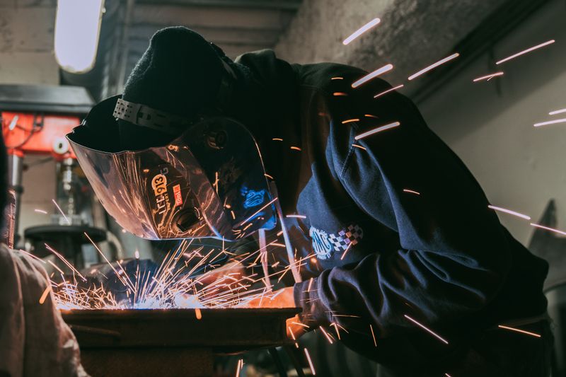
MIG welder popping and sputtering: Diagnose it in 7 checks
A MIG welder that keeps popping, stubbing, or cutting in and out has an unstable arc or an interrupted delivery system. The fastest diagnosis is to return to a documented baseline, then check the work circuit, settings, wire path, shielding, polarity, and technique one system at a time.
Do not chase a “perfect sound” by spinning both controls. In short-circuit gas metal arc welding (GMAW), a fast, even crackle can be normal. Slow hard bangs, wire pushing the gun away, burnback into the contact tip, or repeated arc loss are the useful clues.
Match the sound and behavior to the first check
| What happens | Likely system | First isolation check |
|---|---|---|
| Wire hits the plate and pushes the gun back | Voltage and wire-feed relationship, or feed surging | Return to the door chart; watch whether wire delivery is smooth before changing a setting |
| Arc is stable, then cuts out and restarts | Wire path, work connection, trigger, thermal protection, or input power | Stop and inspect external connections and the de-energized feed path |
| Wire burns back and fuses to the tip | Contact tip, intermittent feed, very short stickout, or parameter mismatch | Replace a damaged tip with the specified size and verify smooth feed |
| Popping comes with pinholes or a sooty, porous bead | Shielding loss or contamination | Check gas delivery, drafts, nozzle condition, and surface cleanliness |
| The problem occurs only over paint, rust, or mill scale | Arc continuity and contamination | Prepare a clean test area and attach the work clamp to clean metal |
| Breaker trips, output fades, a cable overheats, or the machine smells hot | Input circuit, duty cycle, damaged connection, or internal fault | Stop using the machine and follow the manual’s service path |
Make the area safe before troubleshooting
Wear the helmet shade and eye, hearing, hand, body, and foot protection required for the process and hazard assessment. Keep your head out of the plume and use suitable local exhaust or general ventilation; a fan that blows shielding gas away from the joint is not a ventilation solution.
Remove or protect combustibles, check the opposite side of the work, and follow the site’s hot-work permit and fire-watch requirements. Unknown coatings, galvanized metal, stainless steel, confined spaces, and contaminated containers need a specific fume and hot-work assessment—not a quick test bead.
Before touching the spool, drive rolls, liner, gun front end, or connections, release the trigger, turn the welder off, disconnect input power, and follow workplace lockout/tagout rules. Never remove power-source covers, bypass an interlock, or probe energized internal components unless the manufacturer permits the task and you are qualified to perform it.
1. Restore a documented starting point
Record the base metal and thickness, joint, wire classification and diameter, shielding gas, polarity, voltage/tap, wire-feed setting, gun, contact tip, and extension-cord or generator setup. Photograph the spool label and parameter chart.
Use the chart inside the machine, the current owner’s manual, the wire data sheet, or the approved welding procedure specification (WPS) as the starting point. The MIG welding settings chart explains the relationship, but it cannot replace machine-specific ranges.
2. Clean the work connection and weld area
The arc circuit runs through the electrode, arc, workpiece, and work lead. Clamp the work lead where the machine manual permits, as close to the weld as practical, on clean bare metal. Inspect the clamp jaws, cable, lug, and accessible connections for looseness, damage, heat discoloration, or contamination while the machine is de-energized.
Then prepare the joint and test-coupon surface. Remove oil by an approved method before grinding; clean away paint, rust, and scale to the procedure’s requirement.
If the popping disappears on clean scrap with a sound work connection, the original surface or return path—not the welder’s controls—was the likely variable.
3. Balance voltage and wire feed without guessing
In constant-voltage GMAW, voltage and wire-feed speed work as a pair. Miller’s parameter guidance notes that an arc that stubs into the work may need more voltage, while an erratic arc that burns near the tip may need less. Those are diagnostic directions, not universal settings.
Use matching scrap and the documented starting range. Change only one control by the smallest available increment, make a short bead, and record what changed:
- If the wire repeatedly drives into the work, verify that the feed is mechanically smooth. Then correct the voltage-to-wire-feed balance within the machine or procedure range.
- If the arc lengthens and the wire burns toward the tip, return to the baseline and correct the opposite imbalance rather than making a large compensating change.
- If neither direction produces a stable arc, restore the baseline and continue through the system checks.
Do not approve a weld by sound alone. Bead profile, fusion, penetration, discontinuities, and any required destructive or nondestructive tests still control acceptance.
4. Prove that wire delivery is smooth
With power isolated, confirm that the spool brake, drive-roll groove and profile, inlet/outlet guides, liner, gun routing, and contact tip match the wire. Look for a kinked cable, packed shavings, rusty wire, an oval or loose tip, excess roll pressure, or a birdnest beside the feeder.
Lay the gun cable as straight as practical for a controlled test. Reassemble every guard before restoring power, then perform only the cold-feed test described by the manufacturer. The full MIG wire-feed troubleshooting sequence covers spool-to-tip faults in detail.
5. Verify shielding at the nozzle
For gas-shielded MIG welding, confirm the correct gas is connected, the cylinder valve and regulator/flowmeter are operating as intended, hoses and gun connections are intact, and gas reaches a clean nozzle. Check for drafts and an excessive gun angle or stickout. Use the manual or WPS value; the MIG gas-flow guide explains why simply increasing flow can create turbulence rather than solve coverage loss.
Popping by itself does not prove a gas problem. Shielding loss becomes more likely when it appears with pinholes, porosity, oxidation, or a change in sound after moving outdoors. Never check a suspected gas leak with a flame, and secure cylinders with caps fitted during transport.
If you are actually using self-shielded flux-cored wire, there is no external shielding-gas system to test. Verify the exact wire, polarity, drive-roll type, and manufacturer instructions instead; do not apply solid-wire MIG assumptions to FCAW.
6. Confirm polarity and every consumable match
Compare the lead connections with the diagram for the exact wire and process. Solid-wire GMAW commonly uses electrode positive, while some self-shielded flux-cored products use electrode negative, but the label, manual, data sheet, and WPS decide the setup.
Verify that the selected program, wire diameter, drive roll, liner, tip, gas, and base metal also agree.
The MIG setup guide provides a full pre-arc check. Make corrections only with the power isolated and according to the equipment instructions.
7. Check technique, input power, and service limits
Hold the gun angle, travel speed, and contact-tip-to-work distance specified by the wire guidance or WPS. Test from a supported position so an unsteady hand does not repeatedly change stickout. If the problem follows one gun position or cable bend, stop and inspect the gun rather than welding through it.
Confirm the supply circuit, plug, receptacle, generator, and extension cable meet the manufacturer’s input requirements. Do not fit a larger breaker, defeat protection, or improvise an adapter to stop nuisance trips. Let thermal protection complete its prescribed cooling cycle and keep air paths clear.
Arrange qualified service if the trigger is intermittent, a breaker repeatedly opens, insulation is damaged, a connector overheats, smoke or a burning odor appears, the feed motor fails, or output remains unstable after the external systems are verified.
Next step: prove the correction on a coupon
After the arc becomes stable, restore the documented job settings and make a representative practice coupon when the procedure allows it. Record the final voltage, wire feed, gas, polarity, stickout, travel, and observed bead condition. Then apply the inspection and acceptance criteria for the job; the weld-defect guide can help name visible symptoms, but it does not qualify a weld.
For structural, pressure, vehicle, lifting, fall-protection, or other failure-critical work, use an approved WPS, qualified personnel, traceable consumables, and the required inspection. A smoother sound is evidence that the process changed, not proof that the weld is safe.
Sources and scope
- Miller GMAW handbook: transfer modes and normal short-circuit sound
- Miller: setting the correct MIG welding parameters
- Miller: troubleshooting common MIG weld defects
- Lincoln Electric Magnum Pro torch manual and troubleshooting table
- OSHA welding ventilation requirements
- OSHA welding fire-prevention requirements
Manufacturer instructions, regulations, codes, and approved procedures can change. Use the editions, exposure controls, and requirements that apply to the worksite and weld in front of you.

The Welder's Guide Editorial Team
Independent trade-focused editorial team